
Essential Compliance Guide for Transmission Line Tower Design in India
Transmission lines are the main units of the power infrastructure in India. They carry high-voltage electricity from power plants to substations and then to distribution networks. Transmission tower designs followed by EPC companies, utilities, and developers, must be in conformity with BIS standards for transmission towers, regulatory approvals for high-voltage transmission corridors and CEA transmission line guidelines India.
This blog looks into the compliance environment of the transmission line tower projects which include:
- The design standards for the core structures and the electrical part
- Right-of-way (ROW) regulations and land acquisition rules
- Safety measures in the high-voltage corridors
- Guide for the installation of towers and foundations
- Environmental releases and sustainability mandates
- Protocols of quality assurance and testing
By implementing these rules, project developers will be able to receive their regulatory approvals on time, reduce their risk of operational incidences, and be in line with the policies at the national and state level that regulate India’s transmission network.
Regulatory Framework Governing Transmission Line Tower Design in India
The regulatory ecosystem– Indian transmission tower design standards is multi-layered. It consists of the national authorities like CEA transmission line guidelines India and BIS standards for transmission towers at the top as the main regulators. Alongside them are state transmission utilities, SLDCs, forest departments, aviation authorities, and local urban bodies whose permissions are mostly necessary for the implementation.
Core Indian Design Standards and Compliance Codes
Indian transmission tower design mainly depends on the below-listed BIS codes and standards:
| IS Code | Subject Matter | Key Focus Areas |
|---|---|---|
| IS 802 | Structural Construction | Bracing patterns, load combinations, and safety factors. |
| IS 5613 | Overhead Line Construction | Clearances, sag-tension, and OPGW installation. |
| IS 875 | Design Loads | Wind zones, dead loads, and seismic requirements. |
| IS 6533 | Tower Foundations | Geotechnical requirements and foundation types. |
| IS 398 | Galvanization | Anti-corrosion and zinc coating thickness. |
On their own, these BIS standards assure the mechanical dependability, electrical safety, and long-term durability of extra-high-voltage transmission corridors
CEA and BIS Requirements for EPC Developers and Utilities
The Central Electricity Authority (CEA) establishes the compliance regulations that cover:
- CEA (Measures relating to Safety and Electric Supply) Regulations
- CEA (Technical Standards for Construction of Electrical Plants and Electric Lines)
- CEA (The technical grid connection standards)
The essential items covered by the laws are:
- Voltage-Specific Design Requirements: To be covered in the case of towers: Conductor spacing, minimum approach distances, electrical clearances from ground and objects, insulator string specification.
- Right-of-Way and Horizontal Clearances: As an instance:
Voltage Level (kV) Recommended ROW Width (meters) 66kV 15m 132 kV 27m 220 kV 25-28m 400kV (Single Circuit) 35m 400kV (Double Circuit) 46-52m 765 kV 64-85m
- Safety Regulations:These include: Live-line maintenance SOPs, insulation coordination, earthing and grounding standards, safe working distances
- Mandated Documentation for Approvals:EPC companies are required to submit: Detailed project reports (DPR), soil investigation reports, tower design calculations, sag-tension charts. route alignment maps. environment and forest clearances, prototype test certificates.
Structural Design Compliance for Electrical Transmission Towers

Structural design compliance is the core that runs through every transmission line project in India. The very different weather-related issues of the country - high-speed cyclones on one side and very strong seismic belts on the other - make the Electrical transmission tower structural design India subject to very strict standards set by both BIS and CEA for the safety of the people and the grid but also for the long-term viability of the system. Addressing this problem, engineers have to incorporate requirements related to wind and seismic loading norms for towers.
Wind, Seismic, Load, and Conductor Tension Requirements
While seismic and wind forces impact transmission towers heavily, there are other aspects to consider as well. India’s official wind and seismic loading norms for towers dictate how these structures should behave:
- Wind Load Requirements:The country is divided into several wind zones, and every zone requires special designing considerations to be taken. What is instructed by IS 875 is that engineers should take into account basic wind speed, terrain category (urban, rural, coastal), topography effect like hills or ridges, and also the dynamic response of the tower.
States hit by cyclones such as Odisha, Andhra Pradesh, and Tamil Nadu are in for larger safety multipliers because of strong gusts and storm surges whereas desert areas like Rajasthan and Kutch are putting their safety multipliers on rapid gusting and turbulence caused by the scanty terrain. Proper fulfillment of the wind load requirements is what guarantees that the towers will be standing even after the most extreme winds. - Seismic Load Requirements:India’s seismic guidelines, that are based on IS 1893 and IS 875 (Part 5), require that towers be built in such a way that they are able to resist the earthquake horizontal forces. The towers situated in Zones IV and V of seismic earthquakes are supposed to have ductile detailing, stiffer bracing, and stronger joints to avoid brittle failure.
Foundations located in the Himalayas have to be deeper to resist lateral accelerations and ground movements. Seismic compliance plays a very important role in lessening the chance of grid outages that have a domino effect and take place in regions where earthquakes frequently occur. - Mechanical Load Requirements:Mechanical loads defined in IS 802 are the self-weight of the tower, the weight of the conductor and the insulator, the wind load on the conductor, the stressing of the angle tower, and the very important "broken wire condition" whereby the tower, in a situation of one side wire being broken, has to be stable. Establishing river crossings that are of long span is the practice that consequently requires super strong and complex solutions due to the wind and tension that are coming from those spans.
- Conductor Sag-Tension Requirements:The determination of the work to be done by each tower, in other words, the height, the length of the insulator string, the phase spacing, and the foundation forces, are all achieved through calculations of sag and tension. Among other things, these calculations are based on the usage of a certain type of conductor (e.g., ACSR, HTLS, ACCC), span length, temperature, and wind speed.
When the conductor is at its maximum sag, the clearances still have to meet the safety regulations put forward by the CEA and that is, there should be no danger for people, vehicles, or buildings under the conductor.
BIS and CEA Norms Based Structural Optimization
After the establishment of the basic loads, comes the task to optimize the project through changes in the materials, the structure and the foundation of the tower, thus ensuring that the project is in accordance with the norms set by BIS and CEA as well as being economical and environment-friendly.
- Tower Geometry Optimization: Depending on the ground, angle, and weight the designers might opt for one of the following geometries of the towers: Normal square lattice self-supporting towers for most routes, towers with narrow bases for crowded urban areas, towers with wide bases for river spans or very long spans, monopoles where the land cannot be used for more than a few meters. A properly optimized geometry leads to the use of less steel but the efficiency of the structure is higher.
- Material Optimization: To lessen the member size and the weight as well without losing strength high-tensile steel grades such as Fe 410, Fe 450, and Fe 500 are used. As a result, the tower is significantly better off under the different loads - wind, seismic, and vibration.
- Foundation Optimization: Foundation work is largely dependent on the soil bearing capacity and the landscape. The most commonly seen in Indian projects are:
- Pad & chimney foundations for normal soil
- Piling foundations for weak or waterlogged soil
- Raft foundations on rocky surfaces
- Well foundations for river and nala crossings
- Anchor-block foundations for the mountainous regions
A good soil investigation coupled with correct load modelling is a ticket to a safe base for many years to come.
- Fatigue and Dynamic Load Analysis: Towers experience these continuous vibrations that are caused by wind-induced oscillations, conductor galloping, aeolian vibrations, and torsional effects. Fatigue-sensitive parts will be identified in the dynamic load analysis and this will also be the unit that joins them, especially along long corridors and in regions that are very windy.
- Corrosion Protection: Corrosion constitutes one of the major factors that diminish tower life, especially for those that are located in coastal zones, are around industrial areas or live in humid regions. Galvanization is usually recommended ranging between 80–120 microns depending on the corrosion category and environmental exposure. This can be the difference between the normal life of the tower and life extended by 20–25 years.
Right-of-Way, Land Acquisition, and Clearance Norms
Planning the right-of-way (ROW) affects engineering feasibility, community acceptance, safety performance, and even long-term maintenance access. Right-of-way and land acquisition rules for transmission lines go hand-in-hand, and are influenced by CEA safety rules, the Indian Telegraph Act, state-level guidelines, and the environmental and forest clearance framework. For EPC companies, knowing these regulations beforehand is a way to avoid delays, lessen the disputes over compensation and make the social-environmental approval process smoother.
Essentially, ROW is about the horizontal distance or a safety corridor within which a transmission line can be installed and operated. The width of the corridor is largely determined by the voltage of the line: about 15 m for 66 kV, 27 m for 132 kV, 35 m for 220 kV, 46 m for 400 kV, and from 64 to 85 m for 765 kV lines depending on tower type, conductor bundle, and terrain. These widths are there to provide safety and clearance requirements for overhead lines and maintenance without the risk of land uses or structures being close to the conductors.
ROW Standards, Corridor Widths, and Statutory Rules
India's ROW (Right of Way) system is a good example of how a technical safety issue can be balanced with a minimal impact on the communities and landowners. Even though the Indian Telegraph Act gives the power to the utilities to put up transmission lines without the need for land acquisition, the states have created organized ROW compensation policies in order to deal with social fairness. These usually provide for payments for the tower base area, crop damage, and the corridor-based compensation that corresponds to the temporary land-use restrictions.
ROW planning is required to consider many statutory interfaces as well:
- Railway and highway crossing rules (specific clearance and span requirements)
- Airport Authority of India (AAI) regulations concerning height limitations near airports
- Irrigation, PWD, and water resource departments for canal and river crossings
- Oil, gas, and petroleum safety regulations for areas surrounding pipelines
- Municipal and urban development regulations in the thickly populated city areas
Each of these adds different clearance aspects which is why the early survey planning, digital route optimization, and stakeholder consultations are so important for project timelines.
Electrical Safety Norms and Mandatory Clearances for Overhead Lines
Safety clearances for overhead lines, which are mainly specified under the CEA (Measures Relating to Safety and Electric Supply) Regulations, serve the purpose of ensuring that the conductors, under the most extreme conditions of sag and swing, are always at a safe distance from the earth, buildings, roads, railways, and green areas. Besides this, they also set limits for the closest approach of the maintenance teams to the live parts during the wor
Vertical clearances are a kind of protective measure for vehicles and boats as well as for the people who are generally using the railway crossings, national highways, and major waterways. Horizontal clearances are a kind of guarantee that the structures, cranes, and the adjacent industrial units will not cross the boundary lines of the danger zone. The compliance of vegetation and trees is also very strict, with mandatory periodic trimming near the energized corridors, compensatory plantation for the removed trees, and strict regulation within the forest areas.
These clearances are a direct factor in determining tower height, span length, insulator string design, and sag-tension calculations. Properly kept clearances not only lower the risk of flashover but they also increase the grid's capacity to withstand the storm and thus, protect the communities living in the vicinity of the grid from these natural calamities.
Foundation Design and Construction Compliance for Transmission Towers

Foundation design is essentially the support that is not visible, but it is there, the transmission infrastructure. Tower failure originates from foundations before structural faults; deficiencies in the foundation caused by weak soil, poor workmanship or unusual weather are the root causes of these failures. That is the reason the Tower foundation design guidelines India, focuses on thorough geotechnical investigation, prudent foundation type selection and rigorous compliance with construction standards.
Soil Testing, Geotechnical Assessment, and Foundation Selection
Before deciding on the final tower location, EPC teams need to deeply understand the ground through a geotechnical investigation. Besides standard penetration tests (SPT) which measure soil density, plate load tests for bearing capacity, and grab sampling for soil strata, moisture content, and groundwater levels are among the chief tests.
Besides these, in earthquake areas, the risk of liquefaction and lateral load resistance are also evaluated by engineers. The foundation choice depends on these results:
| Soil/ Terrain Condition | Recommended Foundation Type |
|---|---|
| Normal Soil | Pad & Chimney |
| Marshy/ Low-bearing Soil | Pile Foundations |
| Shallow/ Rocky Soil | Raft or Block Foundations |
| Riverbeds/ Alluvial Stretches | Well Foundations |
| Hilly/ Mountainous Terrain | Anchor-block or Stepped Foundations |
| Black Cotton Soil | Under-reamed or Stub-anchored Foundations |
The proper foundation type, as it is, limits the risk of settlement over time, avoids tilting due to wind loads and makes sure that the tower can carry vertical, longitudinal, and transverse forces for its entire lifetime.
Reinforcement, Concrete Quality, and Construction Standard
After the selection of the foundation type, it becomes very important to have a quality construction. The reinforcing steel should be in accordance with IS standards, properly spaced, with correct anchorage length and anti-corrosion protection. The concrete grades are generally from M20 to M25, but higher grades are used in coastal or industrial areas where chemical exposure is a concern. Proper curing which is very often neglected due to tight schedules, is necessary to get the design strength.
Another very important element is the stub alignment: the tower legs have to come out perfectly positioned and levelled so that the steel structure can be fitted without overstressing the joints. The backfilling has to be done with the approved soil, properly compacted in layers, and the drainage provisions have to be designed to prevent waterlogging that accelerates corrosion and weakens the soil.
In the end, foundation compliance is about doing the basics consistently and correctly - testing, designing, reinforcing, concreting, curing, and protecting.
Environmental, Forest, and Statutory Clearancesy
Transmission lines may physically be in narrow corridors, but most of the time, they go through forests, wildlife habitats, rivers, agricultural areas, and urban infrastructure. That is why environmental and forest clearances for transmission projects are a very important part of the compliance in India. These approvals ensure that infrastructure development does not endanger the ecological balance, affect the biodiversity, or violate community rights.
MoEF Guidelines, Pollution Control Approvals, and Forest Permissions
Any project that goes through forest land is subject to the Forest Conservation Act, 1980. Obtaining clearances is like a two-phase process-Stage 1 (in-principle clearance) and Stage 2 (final clearance)-and they also need detailed documentation such as route maps, compensatory afforestation plans, and cost-benefit analyses. The developers are paying for Net Present Value (NPV) of the diverted forest land besides they are undertaking compensatory afforestation, generally double the area of the diverted one.
On the other hand, if the case involves batching plants, stone crushing units, or material storage yards, the developers might also be required to get some additional permissions from the State Pollution Control Board (SPCB). Besides, the MoEFCC guidelines regulate the ability of the industries to discharge effluents into water bodies, soil erosion, rights of the tribal community, and construction waste management
Environmentally responsible design i.e., not harvesting timber in the most sensitive parts of the forest or rerouting your line around a big wildlife habitat, will often save you a lot more time and money than just trying to jam through clearance-heavy routes.
Eco-Sensitive Zone Regulations and Mitigation Measures
Transmission paths that are near national parks, wildlife sanctuaries, elephant corridors, tiger reserves, or officially notified Eco-Sensitive Zones (ESZs) have to go through a more detailed examination. In these cases, besides meeting the regulatory requirements, the main goal is ethical infrastructure development.
The mitigation steps normally consist of:
- Bird diverters and reflective markers in avian-sensitive flyway
- Anti-collision devices for large birds such as cranes and storks
- Night visibility enhancements for towers near wildlife routes
- Underground cabling in highly sensitive elephant or tiger movement paths
- Restricted working hours in areas where wildlife movement is high
- Habitat restoration once construction is complete
By following nature’s rules, developers lessen the risk of the conflict in the long run, safeguard biodiversity, and keep the social license to operate of the project.
Quality Assurance, Testing, and Fabrication Compliance
Quality assurance and testing for tower fabrication is applied to check how well the towers are fabricated, galvanized, tested, and inspected before the very first site visit. Indian transmission tower design standards point to steel quality, galvanization thickness, bolt integrity, weld quality, and load-testing as the most critical parameters, stressing that not one of the five can be ignored, since even the strongest design can fail if fabrication isn’t consistent.
Material Standards, Galvanization Quality, and Factory QA
Fabrication is a process that wholly depends on compliant raw materials, and other BIS specifications for structural steel. EPC contractors usually require mill test certificates, traceability records, and third-party QA in order to ensure that materials are constant throughout big orders.
Next to hot-dip galvanization –which is mostly regulated by IS 4759, stands a major compliance milestone. Most utilities, depending on tower location, corrosion category, and utility-specific procurement specs, require a minimum of 80–120 microns of zinc coating. Besides the amount of zinc, the top quality galvanization is also determined by the coating's giving, homogeneity, and the absence of surface defects, which can lead to a reduction of the tower’s lifecycle.
Factory-level quality assurance also includes:
- Dimensional control with the help of templates and jigs
- Testing of bolt and nut hardness in compliance with IS 1367
- Weld procedure qualification records (WPQR)
- Tests for member straightness and hole alignment
- The Assembly of prototype towers (if CEA or the utility norms require it)
A well-managed fabrication line is generally supported by ISO 9001/14001 standards that regulate processes, and the factory can boast automated drilling and cutting systems along with documented inspection protocols.
Site-Level Testing, Inspection, and Pre-Commissioning Requirements
Quality assurance at project locations takes a step further through pre-dispatch inspection, verification of tower parts, and checks of the foundation-to-tower interface. On-site engineers validate the presence of the tower members, turnbuckles, bracings, and fasteners in the light of the approved drawings, because a small mismatch can lead to huge rollouts of structural instability during conductor stringing.
Testing which is necessary for the sites comprises:
- Checking of bolt torqueing
- Stub-to-leg alignment measurement
- Verticality tests after each lift
- Fastener tightening and anti-theft locking
- Galvanization touch-up inspection at joints and cut
Prior to these, EPC groups perform a pre-commissioning audit covering safety clearances, earthing resistance values, insulator connection integrity, anti-climbing devices, and tower identification plates. In addition, a great number of utilities require a final quality dossier to be submitted which contains test reports, certificates, as-built drawings, ROW maps, and CEA-compliance documentation.

Need end-to-end compliant transmission tower engineering?
Speak with our EPC experts today.
Contact Us Now
EPC Compliance Checklist for Transmission Line Tower Projects
EPC compliance checklist transmission lines India not only facilitates the smooth coordination among design, procurement, fabrication, construction, and regulatory teams but also helps in achieving the zero-defect execution.
Mandatory Technical, Legal, and Safety Documentation
Transmission line projects have to abide by the condition of holding an end-to-end compliance file which should be inclusive of:
- Design calculations as per BIS, CEA, wind and seismic loading norms
- Structural drawings, certified by structural engineers who are licensed
- ROW and land acquisition permissions from state authorities
- Environmental and forest clearances (FC, EC, wildlife NOCs)
- Survey sheets, line profiling, and spotting reports
- Material certificates for steel, bolts, cement, and concrete
- Galvanization test reports and factory QA documentation
- Foundation design sheets, soil test reports, and geotechnical data
- Safety management plans, work-at-height compliance, and PPE logs
- Power line safety clearance reports in line with CEA safety regulations
This documentation turns out to be very important during audits by utilities, state transmission agencies, or central inspectors.
Final Compliance Validation for EPC Execution
It is a must for EPC teams to conduct a final validation covering structural, electrical, civil, safety, and environmental parameters before a line is energised. Some of the main checkpoints are:
- Tightening, leg levels, Tower plumb, and verification
- Conductor sag and tension inspections based on approved charts
- Earthing resistance measurements that follow CEA standard
- Clearance validation–trees, buildings, roads, railways
- Corridor width and ROW compliance checks
- Environmental and forest compliance completion reports
- Punch-list resolution from client/third-party QC teams
The compliant EPC handover is a guarantee that the line is in accordance with Indian transmission tower design standards and is fit for safe, long-term use in high-voltage transmission corridors.
Frequently Asked Questions:
About Us
KP Green Engineering Ltd. provides complete engineering and steel structure manufacturing solutions worldwide, serving industries such as renewable energy, telecommunications and beyond.
Get In Touch

Transmission Line Towers

Windmill Lattice Towers
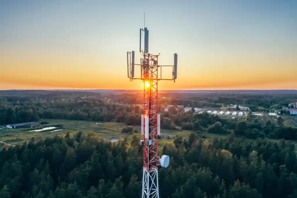
Telecom Towers
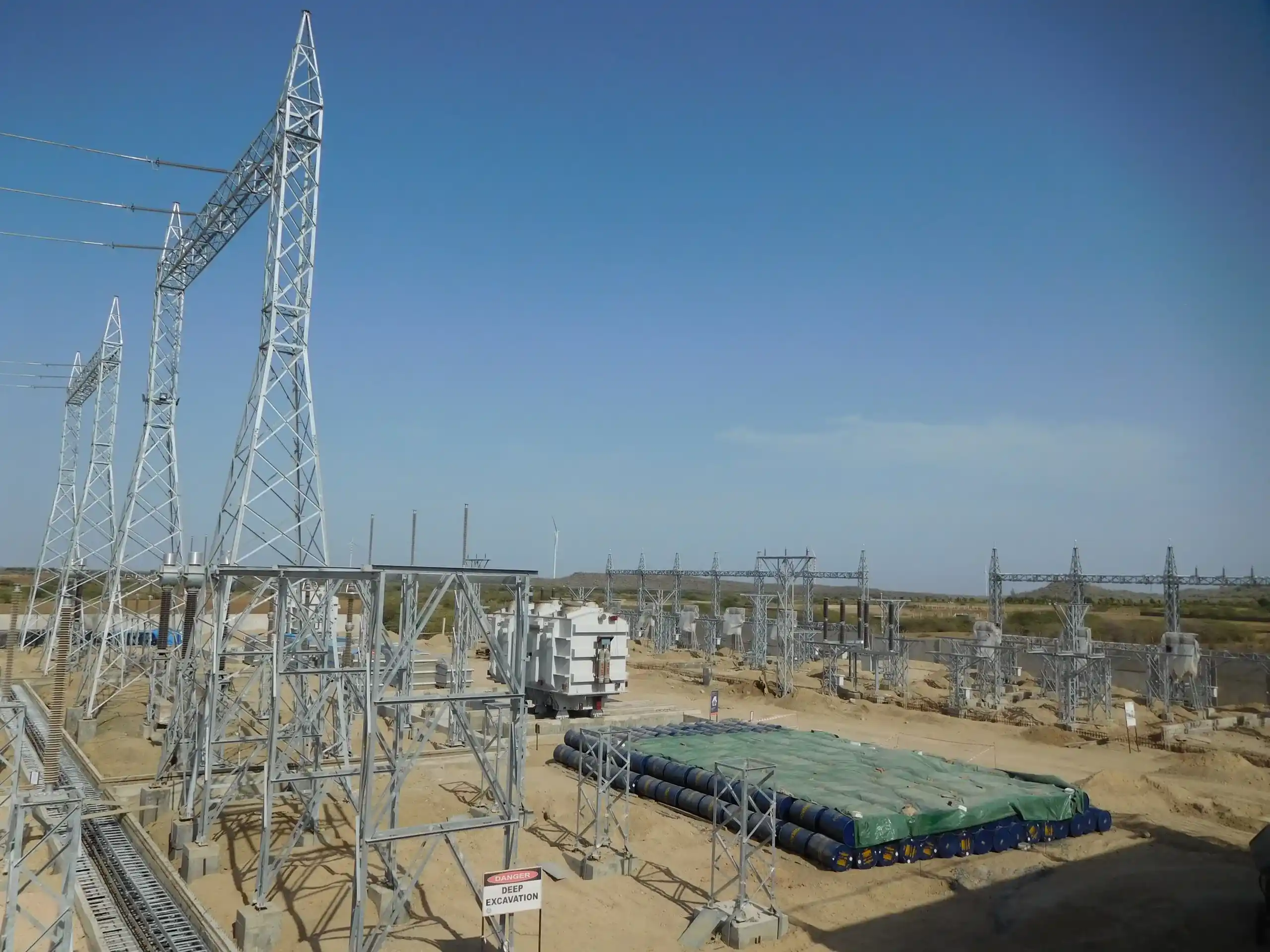
Substation & Switchyard Structures
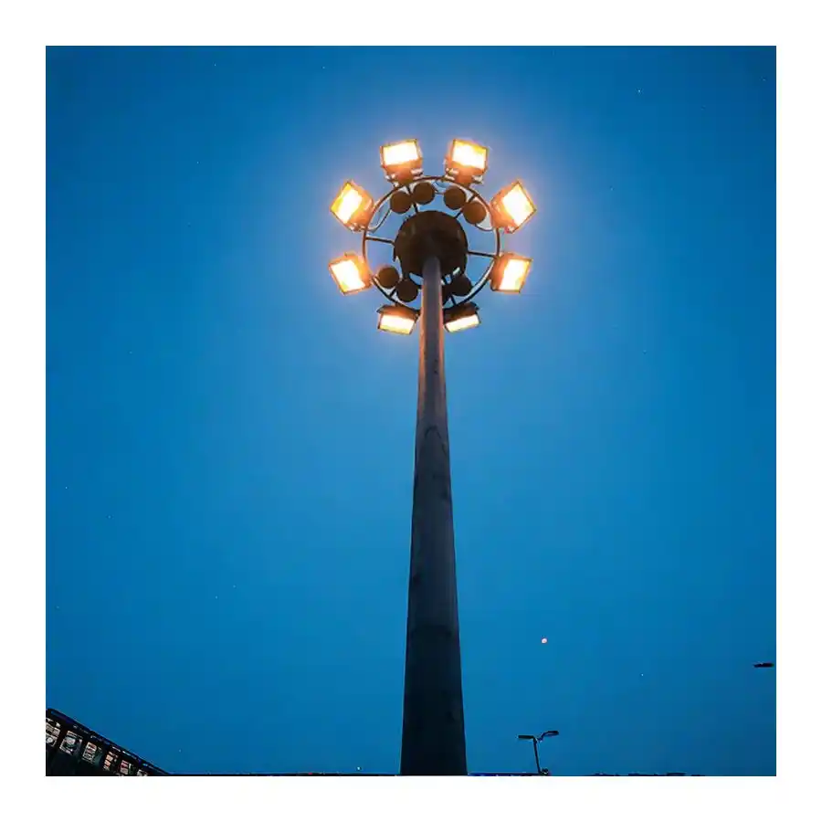
High Mast Towers
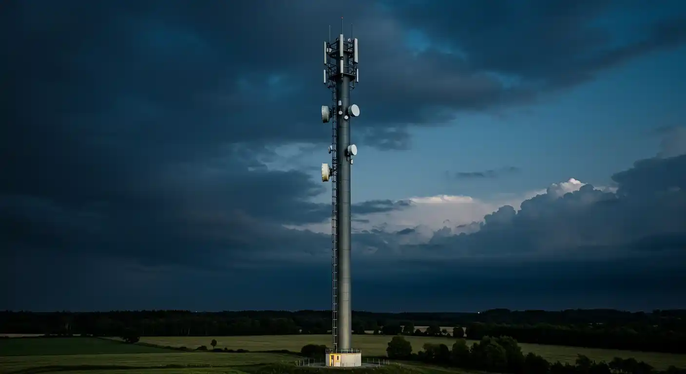
Mono Pole Towers
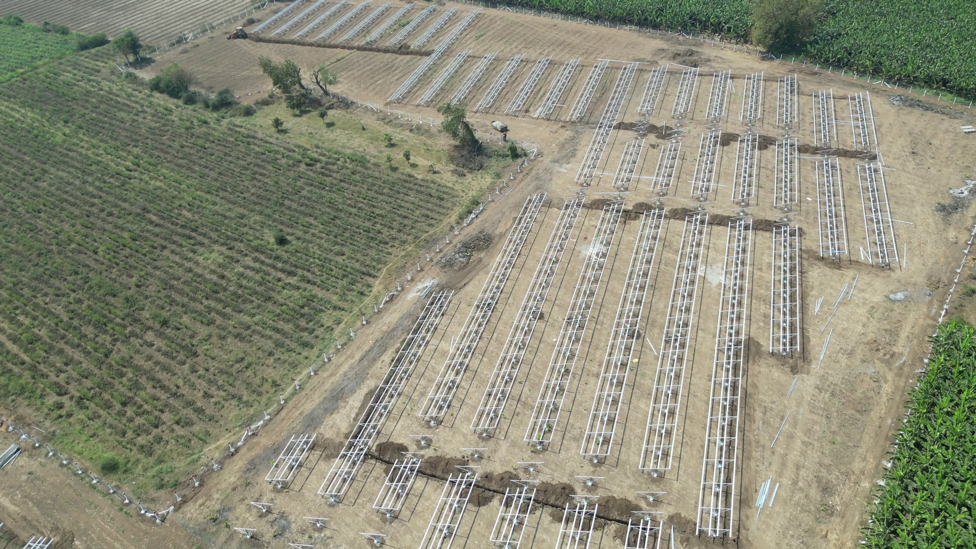
Solar Module Mounting Structures
Solar Trackers

Pre-Engineered Building
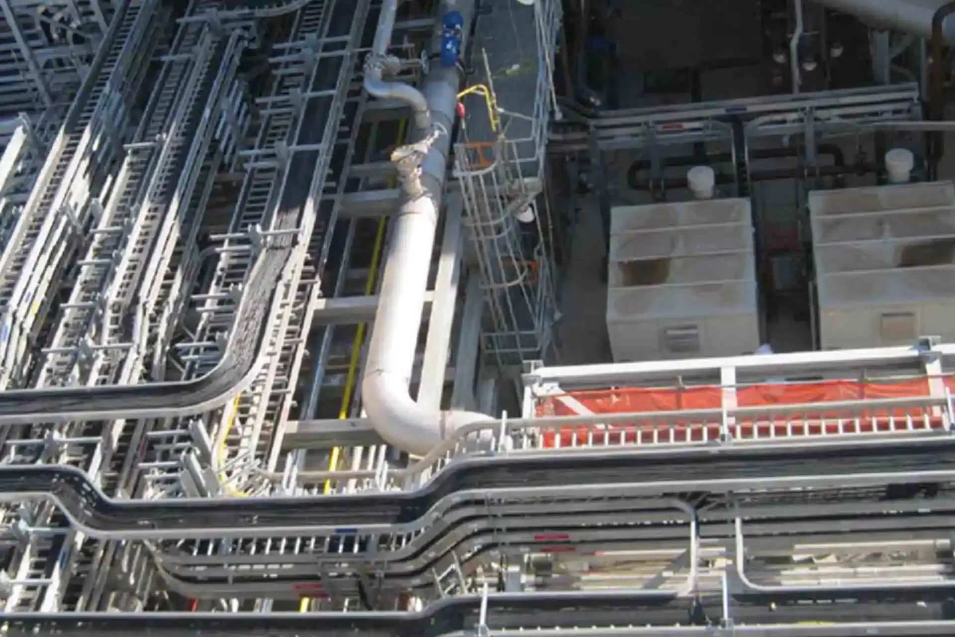
Cable Trays
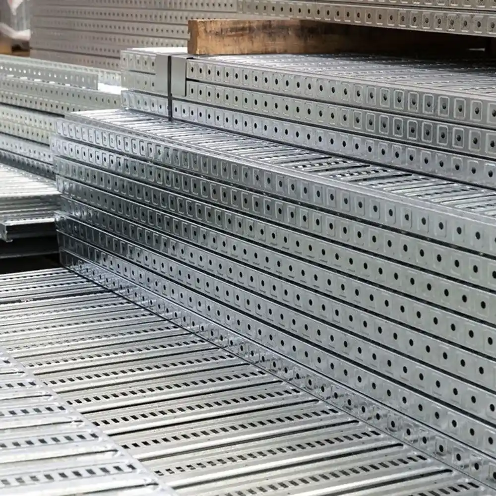
Perforated Cable Trays

Ladder Type Cable Tray

Crash Barriers
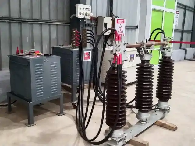
Electrical Isolator

Double Break Isolator/Disconnector
Galvanized Earthing Strips and Flats

Solar Rooftop Solutions
Latest News
What happens when AI meets India’s 300 GW power future
KP Green Engineering Secures INR 239.61 Cr Orders Across Solar, Transmission and Infra Segments
KP Group of Companies Financial Results Announced (FY 2025-26)
Recently Uploaded Blogs


