
How Transmission Line Towers are Engineered for Wind Zones in India
India's extensive geographical diversity poses challenges to power transmission infrastructure, especially where wind conditions are extreme. Transmission line towers in wind-prone regions of India are expected to experience forces that can affect the structural integrity of their components as well as their electrical performance. Examples of challenging locations include the cyclone-prone coastal belts of Odisha and Tamil Nadu, as well as the tops of the mountains in the Himalayas. Designing towers in challenging wind regions requires detailed analysis, adherence to numerous complicated design standards, and the application of engineering judgment to balance safety, cost, and performance
This article attempts to illustrate how engineers design and deploy wind-resilient towers for use across different wind zones in India. It encompasses the look at policy frameworks, foundation alternatives and wind zone applications.
Understanding Wind Zones and Their Impact on Transmission Line Engineering

IS 802 wind zone categorization for transmission towers divides India into 6 wind zones, ranging from wind speeds of 33 m/s in I zone to 55 m/s in VI zone. Each wind zone helps engineers determine the lateral forces towers must resist during extreme weather conditions.
Wind effects on transmission line towers vary spatially. Cyclonic winds develop suddenly in coastal areas, while inland plateau regions experience steady high velocity winds. High altitude regions introduce lower air density and terrain induced turbulence. Spatial variations require more regional design approaches.
Key challenges in critical regions include:
- Coastal zones: Salt-laden winds accelerate corrosion, while cyclones generate multi-directional wind loads
- Cyclone-prone areas: Abrupt wind direction changes and debris impact require enhanced structural robustness
- High-altitude regions: Reduced air density and terrain-induced turbulence.

Understanding these regional nuances enables engineers to optimize tower designs for specific wind load scenarios, ensuring reliability without unnecessary over engineering.
Wind Load Considerations in Transmission Line Tower Design
Design Parameters for High Wind Zones
Transmission tower design for high wind zones begins with accurate wind load quantification. The IS 875 (Part 3) standard provides wind speed mapping, while IS 802 defines wind zones.

Critical design parameters include:
- Basic wind speed: Derived from meteorological data spanning at least 50 years, adjusted for return periods (typically 50 years for transmission infrastructure)
- Terrain category: Classified from Category 1 (exposed coastal areas) to Category 4 (dense urban environments), affecting wind velocity profiles
- Gust factor: Accounts for short-duration wind speed fluctuations that can exceed mean hourly speeds by 40-60%
- Pressure coefficients: Shape-dependent factors determining wind force distribution on tower components
For high wind zones, engineers also consider:
- Wind directionality effects
- Dynamic amplification from conductor oscillations
- Ice loading combined with wind in cold regions
- Topographic multipliers for ridges and escarpments
Structural Stability and Deflection Control
Structural stability of transmission line towers in wind regions depends on controlling static deflection and dynamic movements.
Engineers employ several techniques to enhance stability:
- Optimized bracing patterns: Diagonal members provide triangular geometry that can distribute loads while reducing weight.
- Cross-arm redundancy: Multiple load paths exist to minimize the catastrophic collapse potential of a single member failure.
- Base width adjustment: A bigger footprint of the tower lowers the overall center of gravity and improves resistance to overturning.
- Damping devices: In critical areas, tuned mass dampers or viscous dampers are employed to limit the vibration torque imparted by wind.
Finite element analysis simulates tower behavior under wind scenarios, identifying weak points before fabrication. This computational approach has improved design efficiency, enabling lighter and stronger towers compared to traditional empirical methods.
Engineering Wind-Resistant Transmission Line Towers
Wind-resistant transmission line tower design focuses on minimizing wind loads while maintaining structural adequacy.
Steel windmill lattice towers remain the most prevalent approach in India due to its inherent advantages:
- Open framework allows wind to pass through, reducing drag by 30-50% compared to solid structures
- High strength to weight ratio enables tall towers without excessive foundation loads
- Modular design facilitates transportation to remote sites and rapid field assembly
- Corrosion resistant galvanized coatings extend service life in harsh environments
High-strength structural steel grades like E350 or E410 provide the necessary load capacity while maintaining sufficient elongation to absorb dynamic loads without brittle failure.
Aerodynamic refinements include:
- Tapered geometry: Narrower cross sections at height reduce wind exposure where bending moments peak
- Rounded member profiles: Circular or polygonal sections generate less turbulence than sharp edged angles
- Staggered bracing: Offset connections prevent wind channeling effects that amplify localized pressures
Hybrid designs combining lattice bases with monopole extensions optimize land use while managing wind loads effectively.
Foundation Design for Windy Regions
Transmission tower foundation design in windy regions must resist vertical loads from tower weight and lateral wind forces. Critical cases typically involve uplift on windward legs and compression on leeward legs during maximum wind events.
- Foundation Types (Based on Soil and Load Conditions):
- Shallow spread footings: Used in rock or dense soil, typically 2–4 meters deep
- Pile foundations: Used in soft soils or high uplift zones, extending 8–15 meters to reach bearing strata
- Grillage foundations: Steel frame embedded in concrete for faster construction
- Rock anchors: Drilled and grouted anchors for rocky terrain with high uplift resistance
Transmission tower safety in coastal and cyclone zones demands additional foundation considerations.
- Soil Testing Includes:
- Standard Penetration Test (SPT) for bearing capacity
- Plate load tests for settlement behavior
- Soil chemical analysis for corrosion risk
- Groundwater level monitoring for drainage design
- Anchoring Systems:
- Chimney-type foundations with enlarged bases for uplift resistance
- Under-reamed piles with bulb ends for soil interlocking
- Guy wire systems for load distribution in guyed towers
- Corrosion Protection:
- Cathodic protection systems (sacrificial or impressed current)
- Low-permeability, chloride-resistant concrete
- Epoxy-coated reinforcement in marine environments
- Proper drainage to prevent water accumulation
Engineering Challenges in High-Wind Transmission Tower Projects
- Material fatigue: Cyclic wind loads cause crack propagation; IS 800 design ensures 50 year fatigue life with strict QA for critical joints
- Joint failure: High-strength friction grip bolts and full penetration welds (tested via NDT) prevent loosening and failure
- Long-span instability: Spans >400 m increase oscillations; mitigated using span limits, bundled conductors, or dampers
- Transport logistics: Terrain and access limits require modular components (< 3 tons); remote sites may need helicopter lifts
- Erection safety: High winds restrict lifting; work is scheduled in low wind windows with monitoring and safety systems
- Regulatory issues: Land acquisition and clearances are managed through early stakeholder engagement
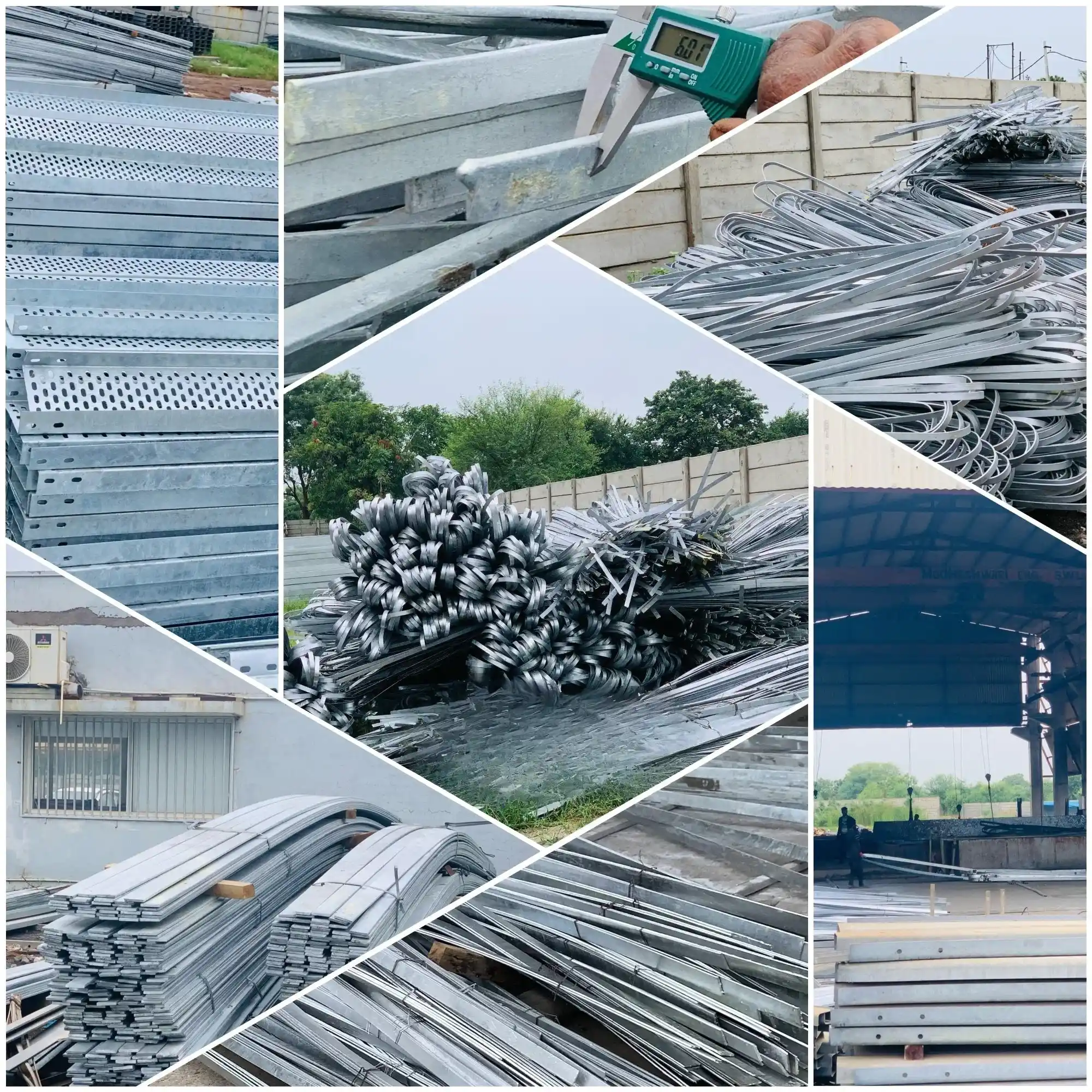
Companies like KP Green Engineering have integrated delivery approaches combining design, fabrication, and field execution to help address these challenges effectively.
Case Insights: Tower Design Innovations for Indian Wind Zones
Real projects show how wind zone challenges are addressed across India:
- Gujarat corridors: Lightweight lattice towers with optimized bracing reduce steel use by 15–20% while maintaining wind resistance
- Tamil Nadu coast: Hot-dip galvanization (≥610 g/m²), deep piles, and cathodic protection for cyclone and corrosion resistance
- Odisha reconstruction: Towers designed for 50 m/s wind with ice loading, improving anchoring and structural detailing
- Hybrid corridors: Compact multi-circuit tower geometries reduce right of way while ensuring wind clearance
- Modular fabrication: Prefabricated components reduce field welding and improve quality control and speed
These innovations reflect continuous advancement in transmission tower engineering driven by climate and technology demands.

Conclusion
The design of transmission line towers for wind areas in India must adopt a holistic strategy combining structural engineering, material science, geotechnical analysis, and construction expertise. Transmission line engineering projects consider wind loading in the design phase, detailed foundation design, and execution, with every stage requiring rigor and expertise.
Key priorities include structural resilience, stability with minimal deflection, and long term sustainability for reliable performance with low maintenance. Achieving this requires close collaboration between engineers, utilities, and fabricators with local expertise.
With rising climate intensity and expanding renewable corridors, demand for improved tower designs will grow, driven by better materials, advanced tools, and field-proven practices.
Specialized engineering organizations play a key role in delivering resilient transmission infrastructure that supports India’s power growth under extreme conditions.
Frequently Asked Questions:
About Us
KP Green Engineering Ltd. provides complete engineering and steel structure manufacturing solutions worldwide, serving industries such as renewable energy, telecommunications and beyond.
Get In Touch

Transmission Line Towers

Windmill Lattice Towers
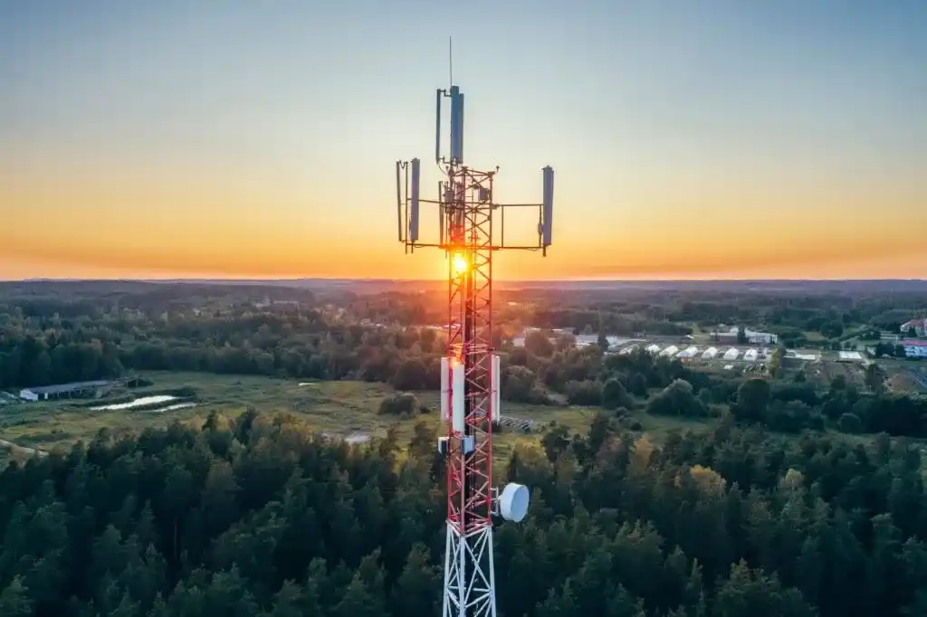
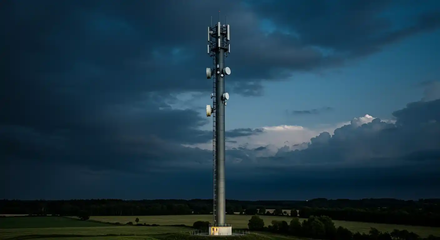
Telecom Towers
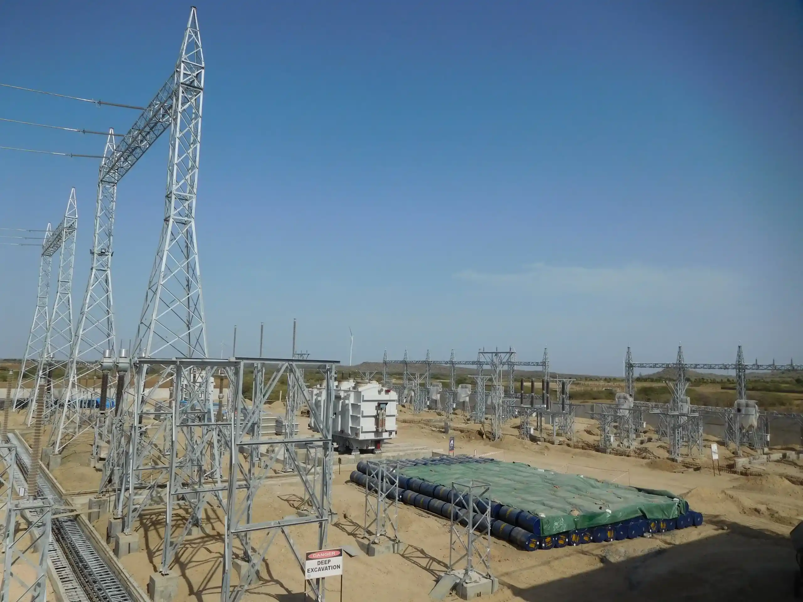
Substation & Switchyard Structures
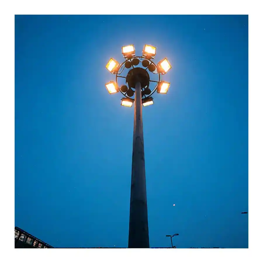
High Mast Towers
Mono Pole Towers
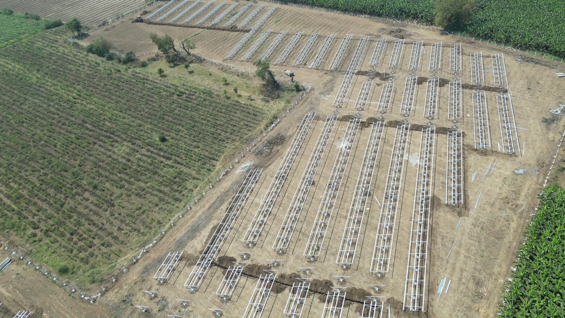
Solar Module Mounting Structures
Solar Trackers

Pre-Engineered Building
Cable Trays
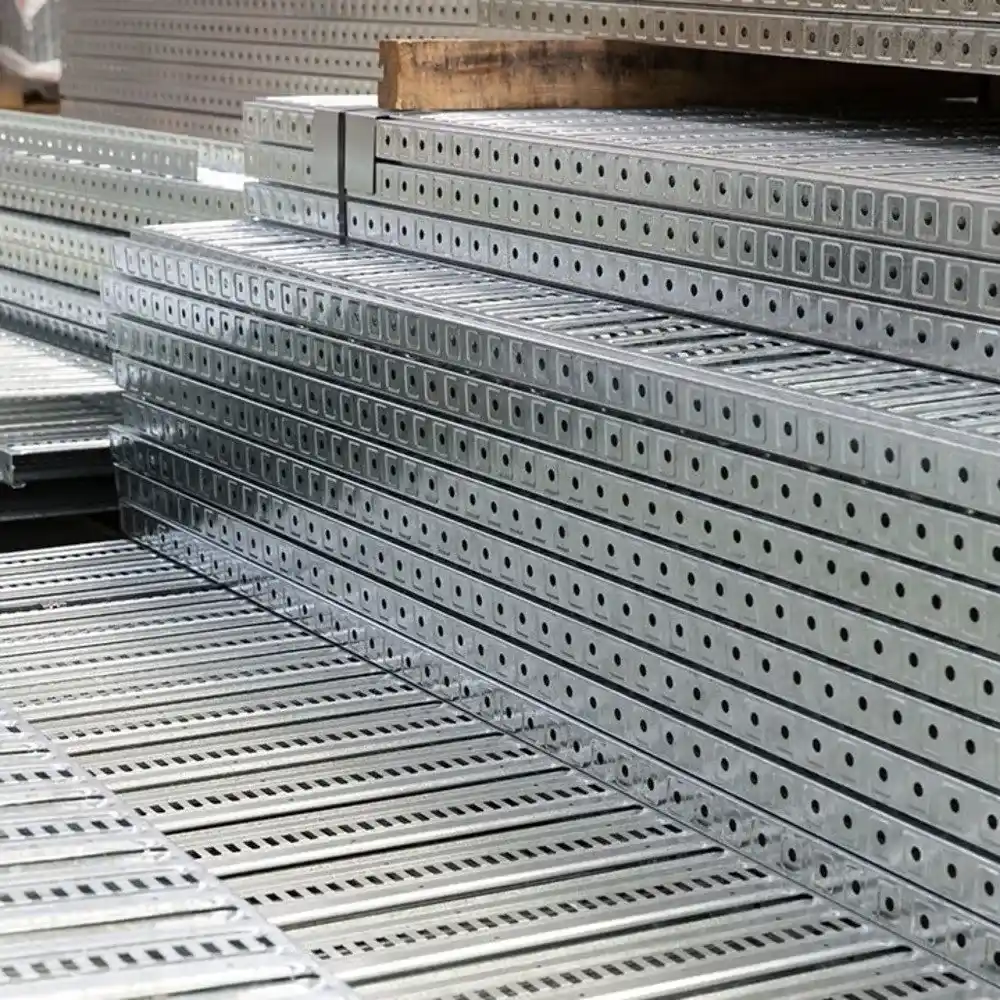
Perforated Cable Trays

Ladder Type Cable Tray

Crash Barriers
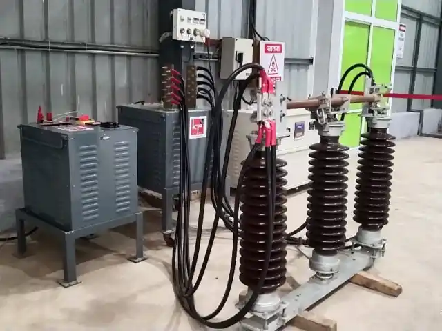
Electrical Isolator

Double Break Isolator/Disconnector
Galvanized Earthing Strips and Flats

Solar Rooftop Solutions
Latest News
KP Green Engineering Secures INR 239.61 Cr Orders Across Solar, Transmission and Infra Segments
KP Group of Companies Financial Results Announced (FY 2025-26)
KP Green Engineering Conducts Groundbreaking Ceremony for Rs 819 Crore BSNL Telecom Infrastructure
Recently Uploaded Blogs


