
Industrial Cable Tray Installation: Best Practices for Long-Lasting Safety & Performance
Although industrial cable tray systems have standardized how cables should be organized and protected at a facility, long-lasting cable tray safety and function have become contingent on how installation is done.
In the real-world setting of a factory or industrial setting, cable tray failure does not generally result from choosing the wrong cable tray, they result from situations where cable tray installation is rushed or misdirected without due consideration for the operation of the system. Drooping cable trays, overheating cables, cable failure due to vibration stresses, as well as premature corrosion are all installation-related problems.
This blog delves into what needs to be accomplished for cable tray installation planning prior to installation, at installation, and post-installation, in order to have high performance levels realized down the road.

Cable Tray Support Spacing & Structural Fixing Best Practices
The most misunderstood method in the installation process is cable tray support spacing.
Horizontal trays usually call for support intervals that are much closer together than one would normally think, especially when the tray is fully loaded. Support intervals should always be determined by the installed load, not the catalog maximum. A longer span may appear to be acceptable when the tray is unloaded but begins to droop when drawn and grouped together.
A vertical tray servery configuration requires a different strategy. The loading process requires vertical support or loading clamps to ensure that no buildup of loading occurs at horizontal joints. Inaccurate vertical support position will compromise vertical support joints to shear failure.
Structural fixing is equally important. The selection of the anchor bolt is dependent on the substrate material. Concrete, structural steel, and composite substrates react differently for dynamic loading. The general use of anchors that ignore the concerns of pull-out resistance, dynamic effects, and resistance to corrosive environments is a common shortcut in anchor installation.
In high-vibration areas, such as in the vicinity of rotating equipment, air compressors, or large machinery, additional precautions must be taken. These involve support intervals beyond building codes or standards, lock-fasteners, and isolation as needed. Vibration-related failures tend to manifest months or even years post-commissioning industrial cable tray installation practices.
Electrical Cable Tray Installation Standards & Compliance
Code compliance in electrical cable tray installation is a major safety check. Earthing and bonding should be carried out while installing the trays and should not be done later on. Every part of the tray, joints, and support points should have good electrical continuity. Inadequate bonding could lead to improper current paths and touch potentials.
Short-circuit force is another area not considered in depth. When there is a fault, there may be electromagnetic force displacement in cables. Suitable clamping and spacing, along with robust tray joints, will guarantee that the system resists these forces without failing.
Fire-rated routing compliance for both the route and the fire zone itself is a function of installation. The consideration of required separation distances to avoid undesired penetrations and fire compartment boundaries is not just a matter of planning and design. A successful route design will not work if shortcuts are taken on site that are not documented.
Lastly, the inspection points installed to a power structure must ensure compliance with cable tray safety standards conducted prior to cable laying, after the erection of the trays, or after cabling.
Heavy-Duty Cable Tray Installation for High-Load Environments
In the power-dense industrial area of data centers, manufacturing facilities, substations, and process plants, heavy-duty cable tray installation requires an entirely different process than conventional tray installations. Because, failure here is often cumulative rather than sudden. It grows slowly in the form of deflections and micro-movements.
Starting with industrial power cable trays, for example, power density represents the initial installation difficulty. Although high current capacity means heavier, stiffer, and less forgiving cable, actual installed weight, trefoil cable groupings, and futures must be considered. Overloaded cable trays do not fail catastrophically but progressively sag long before any apparent sag can be observed.
Sag prevention is thus a matter of installation practice and not a design consideration. Closer support spacing, staggered supports within joint areas, and reinforcement of tray transitions are methods of equal load distribution. In long corridors, it is important to check deflection limits successively as loading progresses rather than at the end of cable installations.
Another aspect which receives little attention is the alignment of the trays over the long span. Even small amounts of trays’ angular misalignment over the long span result in an increase of the concentration of the load after the cables are laid. Alignment by the use of a laser or string line ensures the trays are level and stress-free over the span.
Deflection of load during heavy-duty cable tray applications must actively be controlled during the process. In instances where observable deflection gets beyond acceptable levels during the cabling process, measures must immediately be taken to correct the matter. Inability to act on observable warning signs would easily result in structural fatigue.

Cable Laying, Separation & Bending Radius During Installation
One of the most important points in power cable tray installation is ensuring appropriate separation between power cables and control cables at the point of installation. After laying down cables, it is quite troublesome and costly to make adjustments in cables that are improperly separated. They should make sure not to “adjust” barriers, spacers, or separation points during laying.
Bending radius infraction is yet another frequent costly error. High power cables stretched tightly from tray to tray bends, vertical drops, or offsets cause internal conductor damage or insulation when not easily seen with the naked eye. In the process of installing the cable, the drag and roll position, together with the bend configuration, to maintain minimum bending radiuses, especially when turning direction corners.
Compression errors tend to happen if the weight distribution of the cables is not given due consideration. Putting heavier power cables on top of smaller control or instrument cables causes deformation to the insulation. Moreover, uncontrolled cable crossings during the pulling process result in pressure points, thereby creating friction damage.
Common mistakes found in real-world installations are a result of speed over discipline. Fast pulling, manpower shortages, as well as a lack of supervision during cable installation can negate cable tray installation guidelines.
Corrosion Protection & Coating Integrity During Installation
Corrosion-resistant cable tray installation is less about materials, more about how those materials are treated at the site. Galvanized and coated trays are particularly susceptible to damage during unloading, storage, and erection. Dragging trays across concrete, improper stacking, or striking edges while lifting removes protective coatings long before the system is energized. The bad news is that prevention is always less costly than repair after the fact.
Proper handing and storage practices are the cornerstones of industrial cable tray protection. Trays should be stored off the floor, protected from standing water, and separated from other trays to prevent metal-on-metal abrasion. Installation teams need to treat tray coatings as functional protection, not cosmetic finishes.
Another critical installation step is cut-edge protection. On-site cutting, drilling, or modification exposes bare metal that becomes a corrosion initiation point. Instant treatment of every cut edge with approved zinc-rich or protective coatings is required to restore corrosion resistance.
Compatibility of fasteners is a commonly overlooked but important consideration. Mixing incompatible metals, such as galvanized trays fitted with standard carbon steel fasteners, results in galvanic corrosion pathways. Installation teams must ensure that all fasteners, washers, and brackets match the tray's corrosion protection system.
Ultimately, very few corrosion-related failures trace back to material choice. They trace back to shortcuts taken during the installation of corrosion-resistant cable tray installation, where coating integrity was compromised long before the system entered service.

Installation Quality Checks & Commissioning Before Energization
Cable tray installation inspection is where cable tray installation implementation is cross-checked with design intent.
Final alignment checks must be made. The trays have to be level, straight, and free from torsional stress, particularly in long cable runs and at transitions. Small misalignments at this point can cause problems in loading distribution once it heats up and expands.
Load and support audits are to follow. This is not something that is checked with paperwork. The weight of cables installed must be compared to support spacing. Any indication of impending support or bracket failure or movement of the anchor needs to be remedied to ensure industrial cable tray safety.
Continuity tests for earthing cannot be compromised in an industrial cable tray. Each section, joint, turn, or vertical section in these trays has to ensure electrical continuity. Any loose bond, absent jumper, or painted joint in these sections is dangerous because it disrupts current flow. A structured pre-powered safety checklist allows mechanical integrity, bonding, clearance, and compliance.
Common Cable Tray Installation Mistakes in Industrial Projects
Most cable tray installation errors are the results of speed, poor coordination, or the absence of supervision. Overloading during the installation process remains one of the common industrial electrical installation issues faced. Tray loading occurs when the trays are overfilled during the process of pulling, especially when additional cables are to be installed without considering the loading process.
Inadequate support spacing is another very common error. The cable spacers are based on nominal spacing rather than cable weights, vibration areas, or tray width. When loaded, these issues normally show up as failures.
Inadequate cut edge treatment on bare cut edges result in the exposure of the metal to the environment with the end result being premature corrosion of the tray body.
The potential for serious damage in earthing can be realized in missing bonds, loosely secured fasteners, or a dependence on mechanical connections alone.

Ensure facility safety with our industrial cable tray solutions. Contact our engineering team today.
Contact Us NowConclusion - Why Correct Industrial Cable Tray Installation Matters
Proper cable tray installation in industry has a major impact on long-term safety and cost considerations. Cable trays installed improperly can compromise their integrity and end up a source of electrical hazards and corrosion.
Effective execution during the installation process eliminates rework, helps prevent unplanned shutdowns, and protects people and plants. In the context of industrial facilities, installing it right the first time around means not a cost but a risk management strategy that pays off for decades.
Frequently Asked Questions:

About Us
KP Green Engineering Ltd. provides complete engineering and steel structure manufacturing solutions worldwide, serving industries such as renewable energy, telecommunications and beyond.
Get In Touch

Transmission Line Towers

Windmill Lattice Towers

Telecom Towers
Substation & Switchyard Structures

High Mast Towers

Mono Pole Towers
Solar Module Mounting Structures
Solar Trackers

Pre-Engineered Building
Cable Trays
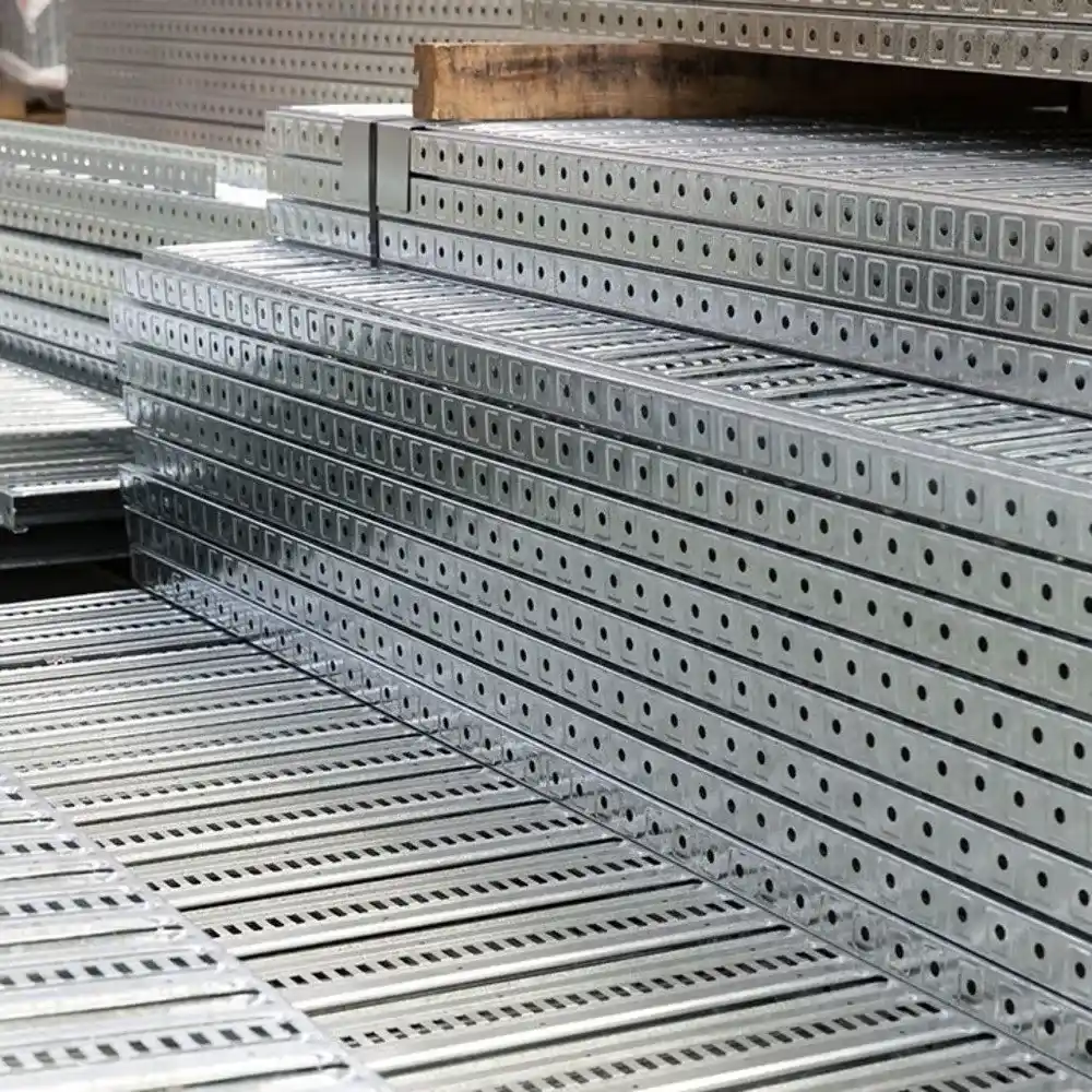
Perforated Cable Trays

Ladder Type Cable Tray

Crash Barriers
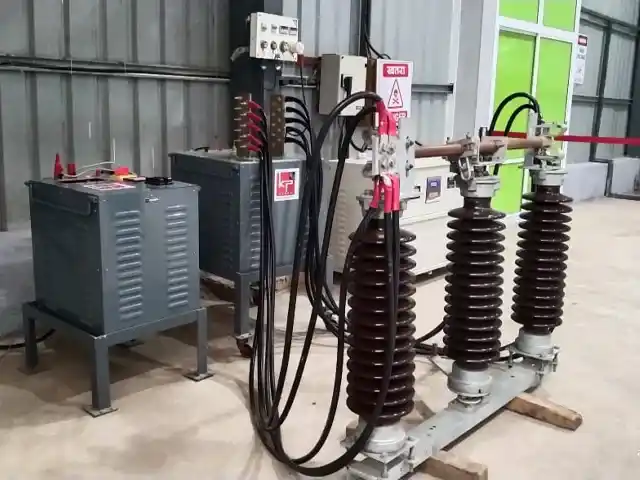
Electrical Isolator

Double Break Isolator/Disconnector
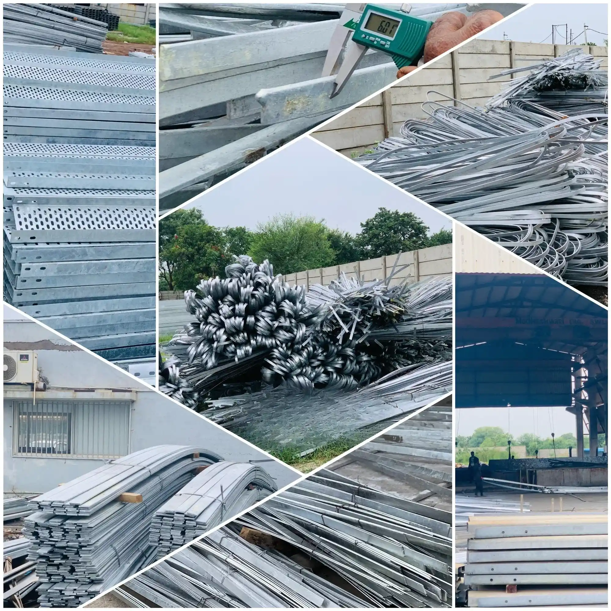
Galvanized Earthing Strips and Flats

Solar Rooftop Solutions
Latest News
Rs 272 Crore Orders! This Green Energy Engineering Stock Wins Contracts Across 3 Key Businesses
KP Group Raises FY32 Ambitions with KP 3.0, Targets 10 GW Each in Owned Generation and EPC
KP Group’s listed renewable businesses post strong multi year growth on the back of disciplined capital allocation, operational efficiency
Recently Uploaded Blogs


