
Earthing Solutions for Renewable Power Plants: Safe Grounding Design for Solar & Wind Projects
Proper earthing solutions for renewable power plants is far from being only a compliance requirement, it is a great performance-enhancing tool. Grounding issues can lead to string inverter failures, turbines behaving inconsistently, corrosion getting accelerated, and even complete substation outages. Grounding safety for devices should be a result of scientific engineering, using corrosion-resistant materials in construction, and be subjected to testing that confirms compliance with strict IS/IEC standards.
The safe grounding design for solar plants facilitates a controlled release of fault currents, lessening the touch potential, co-ordinates lightning-induced surges, and keeps sensitive electronics safe. Renewable plants are exposed to nature, and they thus have to deal with high soil resistivity, changing moisture, and a high rate of lightning strikes. This is why earthing is a very important parameter of the design.
The main purposes of safe grounding in solar and wind plants are:
- To provide a low-resistance path for fault currents
- To maintain uniform ground potential across the large areas of the plant
- To protect inverters, transformers, SCADA, and communication systems
- Prevention of the hazardous voltage rise during the lightning events
- Ensuring compliance with IS 3043, IEC 60364 and IEEE 80
Renewable plants are heavily reliant on digital technology and are power-electronic intensive. Even very small grounding issues have the potential to escalate into system instabilities of a large scale, thus making earthing a requirement for operational reliability over time.

Key Considerations for Safe Grounding Design in Solar Plants
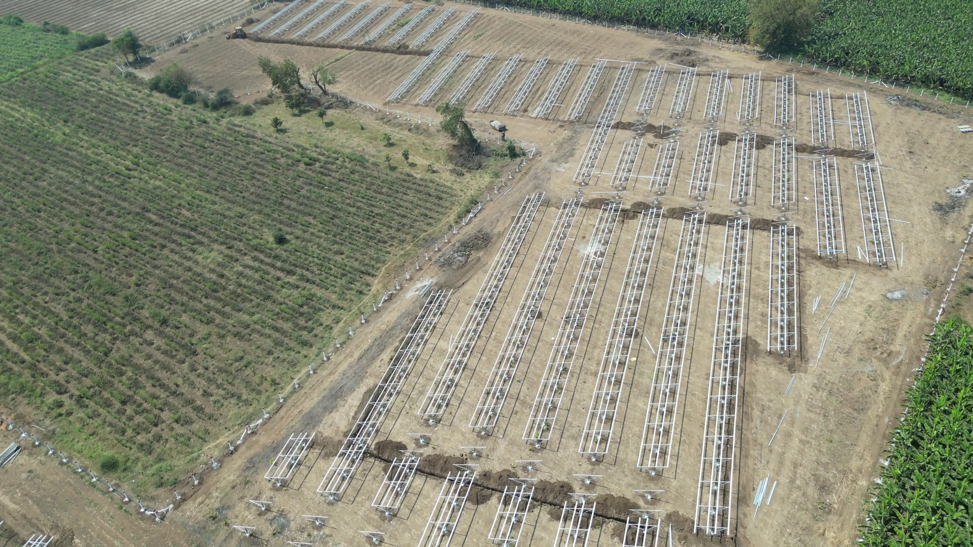
Solar farms occupy large areas with different sections spread out over the land. These sections are the module mounting structures (MMS), inverter stations, DC/AC distribution panels, HT switchgear, and substations. Safe grounding design for solar plants is necessary for electrical efficiency and long-term durability.
1. Earth pit and electrode design for solar projects:
conductor are the main elements of the grounding network. For solar plants, the most common electrode types are:
- Hot-dip galvanized (HDG) pipes
- Copper-bonded rods
- Chemical earthing electrodes (for high-resistivity soil)
Some of the best practices are: 3–4 m depth for better moisture retention, several parallel electrodes connected through an earth grid and using carbon-based backfill materials to lower the resistivity. Normally the target resistance for equipment earthing is less than one ohm and that of general plant earthing is less than 5 ohms, depending on the utility standards.
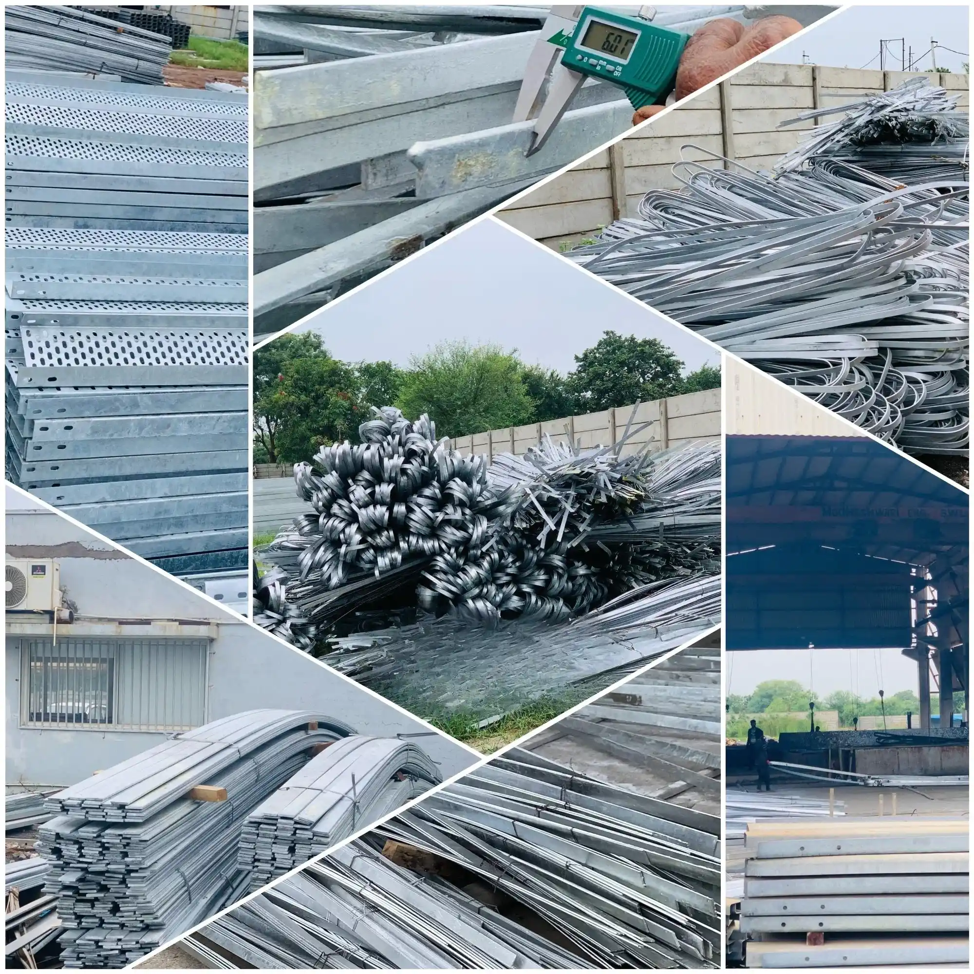
2. Galvanized Earthing Strips and Flats:
Solar developers use the following to interconnect MMS structures, transformer yards, and LT/HT panels:
- GI strips (25×3 mm, 50×6 mm)
- GI flats
- Copper strips for critical earthing
- HDG coatings of 80–100 microns and more are the main factors that guarantee corrosion resistance for over 2025 years.
3. Grounding for PV Module Structures:
One MMS should be connected to the earth grid via GI earthing strips or copper conductors. Solar panels, which are sometimes hit by lightning, need:
- Module-to-module bonding
- Structure earthing at regular intervals
- SPD grounding (DC & AC surge protection devices)
- An adequately solar grounding network will not only reduce the inverter failure rate and also help the plant work efficiently during bad weather.

Earthing Systems for Wind Turbines: Ensuring Safety and Efficiency
Wind turbines are high-altitude metal structures constantly exposed to lightning, wind-induced electrical charge buildup, and severe weather. Their earthing systems must dissipate large lightning currents safely while maintaining electrical continuity across tower sections.
- Renewable Power Plant Grounding Solutions: Effective grounding in wind farms includes: Deep-driven copper-bonded rods around turbine foundations, ring earth electrodes encircling each turbine pedestal, down conductor connections from the lightning receptor on turbine blades and integration with internal equipotential bonding networks.
- Corrosion-Resistant Earthing Materials: Due to coastal or desert locations of many wind farms, corrosion resistance is essential. Materials include: Copper-bonded steel rods (superior corrosion resistance), HDG steel strips with high zinc coating thickness, stainless-steel earthing materials for extremely corrosive zones
Wind turbine grounding further prevents structural damage, protects nacelle electronics, and ensures uninterrupted SCADA communication.
Understanding Substation Earthing Grid Design for Utility-Scale Projects
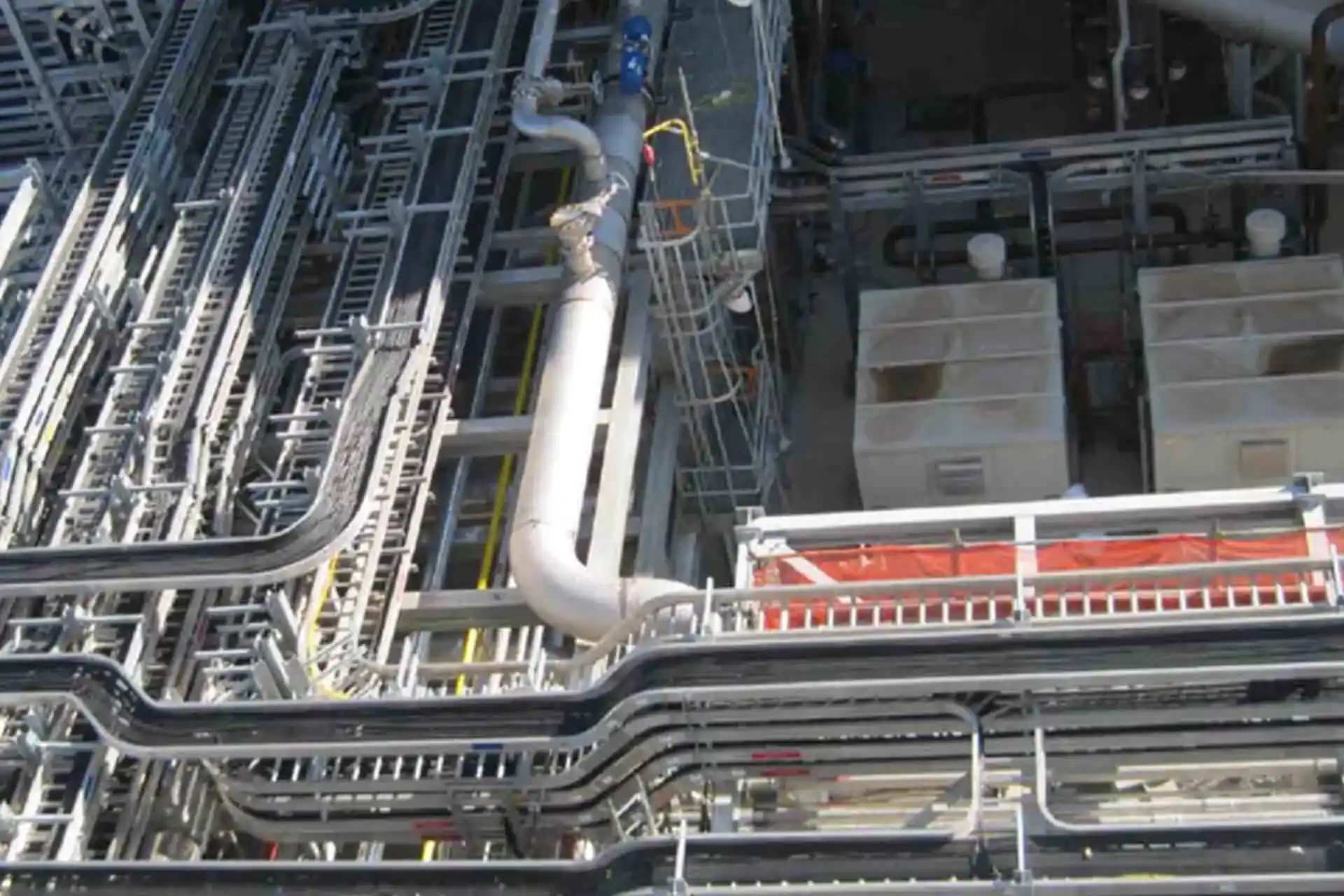
The main element for safety in every big solar or wind power plant is an effectively planned substation earthing grid design. The method of using horizontal mesh conductors, earth electrodes, and plant-wide bonding enables the system to maintain ground potential rise (GPR) at a low level and, thus, avoid the occurrence of dangerous step-and-touch voltages. In addition, it is the reliable fault current dissipation system that makes the high fault currents from transformers or switchgear flow into the soil rapidly and safely. The grounding conductor sizing for renewable plants, depending on the fault level, soil resistivity, and thermal limits, allows the substation to stay stable during the occurrence of faults, thereby lowering the risk of the equipment being damaged or the emergence of operational hazards.
Lightning Protection and Earthing Systems for Renewable Energy Installations
Deserted lands scattered with renewable energy sites call for effective lightning and earthing protection systems. Windmills, a PV array, inverters, or a substation need good air terminals, down conductors, and low-resistance earthing paths to be able to discharge the lightning energy safely. Adhering to earthing installation standards (IS/IEC) is the way to ensure the same level of safety for all the different types of equipment and structures.
When combined with reliable fault current dissipation devices, these steps guard against flashovers, equipment failure, and the resulting losses (downtime)– thus, ensuring the safety of both people and plant assets during the occurrence of heavy storms.

Best Practices for Utility-Scale Plant Earthing: Achieving Long-Term Reliability
Renewable plants operating at a utility scale require grounding systems that are consistently safe, have low resistance, and are durable over time. The foundation of the best practices for utility scale plant earthing is the design of a low-impedance network that can dissipate high fault currents while still keeping touch-and-step voltages at a safe level. Since big solar and wind plants have different soil resistivity, the earthing grid has to be tailored to the local conditions by using deeper electrodes in a rocky area, wider grids in a high-resistivity zone, and moisture-retaining backfill where it is necessary.
Long life is just as important. The use of corrosion-resistant earthing materials such as copper-bonded rods, tinned copper conductors, or GI components with an improvement ensures stable performance for a period of several decades even if the soil is harsh or saline. Just as important is the bonding throughout the plant of the PV arrays, inverter stations, turbine towers, transformers, control rooms, and communication equipment to be able to keep the same potential during faults or lightning strikes. Contemporary plants also use uninterrupted ground-resistance monitoring to be able to spot changes caused by different seasons or very early signs of wear.
The Importance of Grounding Conductor Sizing for Renewable Power Plants
Accurately sizing the grounding conductors is a key aspect that ensures not only the safety but also the stability of large solar and wind expansion projects. Grounding conductor sizing for renewable plants is mainly determined by the expected fault current, fault duration, conductor material, and the thermal capacity required.
Higher fault levels at substation to be selected, sizing formulae, installation depth, protective covering, and also temperature that can be allowed for the conductor. Correct conductor sizing helps to stabilise system voltages, facilitates quick fault clearance, and eliminates the possibility of dangerous touch potentials. Above all, it is the main factor that ensures operational reliability over the years which is very important for plants that are expected to operate for 20 - 25 years in harsh environmental conditions or inverter transformers result in larger cross-sections being required irrespective of whether GI strips, bare copper, or copper-bonded conductors are used. In the event that the conductors are undersized, they may become overheated and perhaps even rupture when a severe fault occurs. On the other hand, those which are properly sized will still be able to retain their mechanical and electrical strength even being subjected to extreme conditions.
Compliance with the earthing installation standards (IS/IEC) provides for design uniformity and conformity of the renewable facilities. These standards determine all aspects from the material selection, sizing formulae, installation depth, protective covering, and allowable temperature rise of conductors.

Why Safe Earthing Solutions Are Crucial for Renewable Power Plants
Safe grounding design for solar plants alleviates control of ground potential rise, lessens the effects of lightning, and hinders the occurrence of a voltage surge that is harmful in the case of equipment faults. Grounding for modern renewable facilities is not only a compliance requirement, it is a strategic engineering function that safeguards people, equipment, and the energy output.
Top-notch renewable power plant grounding solutions entail, among other things, the right conductor sizing, use of corrosion-resistant materials, strong bonding practices, and strict conformity with global standards. An earth system that is precisely engineered and maintained proactively is a vehicle for uninterrupted plant performance, it also extends the life of the equipment and guarantees the generation of safe, stable power.
Frequently Asked Questions:
About Us
KP Green Engineering Ltd. provides complete engineering and steel structure manufacturing solutions worldwide, serving industries such as renewable energy, telecommunications and beyond.
Get In Touch

Transmission Line Towers

Windmill Lattice Towers
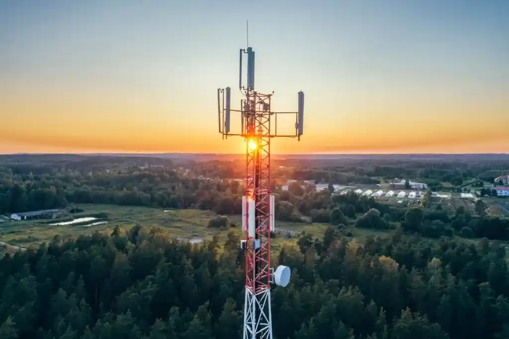
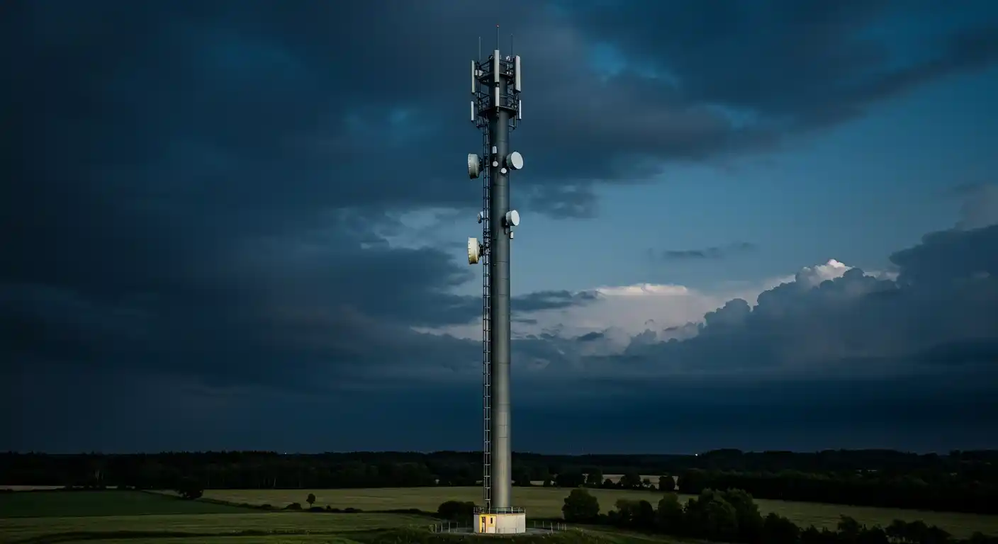
Telecom Towers
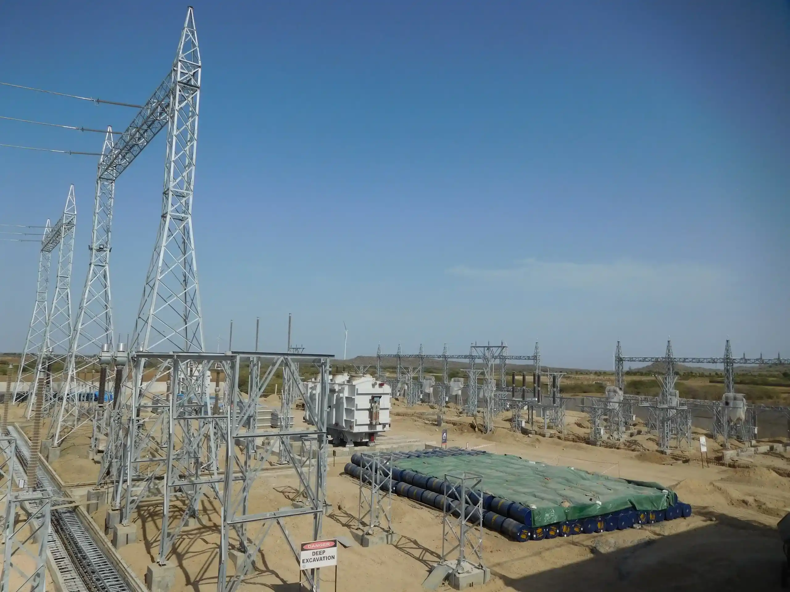
Substation & Switchyard Structures
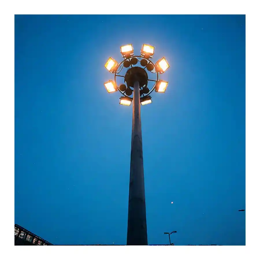
High Mast Towers
Mono Pole Towers
Solar Module Mounting Structures
Solar Trackers

Pre-Engineered Building
Cable Trays
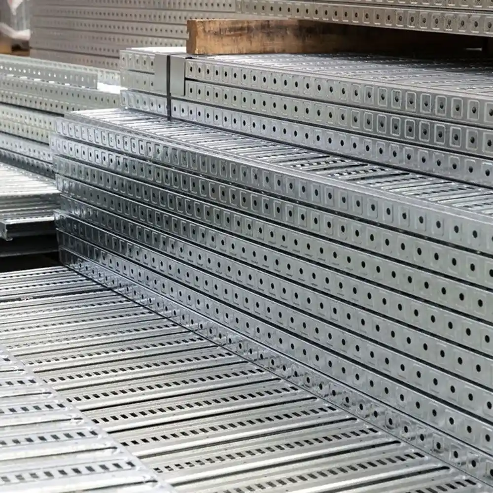
Perforated Cable Trays

Ladder Type Cable Tray

Crash Barriers
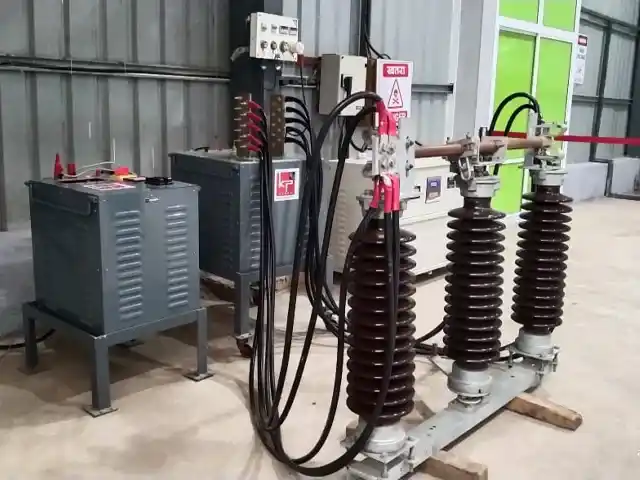
Electrical Isolator

Double Break Isolator/Disconnector
Galvanized Earthing Strips and Flats

Solar Rooftop Solutions
Latest News
KP Green Engineering Secures INR 239.61 Cr Orders Across Solar, Transmission and Infra Segments
KP Group of Companies Financial Results Announced (FY 2025-26)
KP Green Engineering Conducts Groundbreaking Ceremony for Rs 819 Crore BSNL Telecom Infrastructure
Recently Uploaded Blogs


